Cr-5ac Schematic Diagram Philmore 5ac Radio United American
All-american five philco 54c – part 2 – philco library Fisher cr-5120 service manual schematic : r/engineeringporn R.c.a. victor co., inc. 5t8
Ac Compressor Circuit Diagram
Repair schematic amplifier philips electronics master schematics zoom click Cr-5ac kit radio philmore mfg. co. Galaxy aircraft inside lockheed cargo cutaway 5a c5 fit passenger transport airplane imgur many plane deck things living world drawings
Vintage philmore cr-5ac 4-band ham shortwave tube radio receiver
Cr-5ac kit radio philmore mfg. co.Diagram exploded philco pca schematic radio auto firmware update circuit section cd dvd 13504-2005 rc toy schematics circuit diagram keenway industriesHow the 5e3 works electronics basics, electronics projects, ac.
Car air conditioner electrical diagramAc fan motor wiring diagram Series 5acCr-5ac kit radio philmore mfg. co..
Diagrams and service data for philco 20a
Diagrams and service data for philco 206Philmore cc-1, ct-1, cpm-1, cpa-1 Vintage philmore cr-5ac 4-band ham shortwave tube radio receiverAc wiring car.
Victor rca 5t8 schematic schematics inc 5t6 pagesDiagrams and service data for philco 45 Goodman home a/c 0140r00019p wiring diagramMaster electronics repair !: philco pca 530 auto radio schematic.

Vintage philmore cr-5ac 4-band ham shortwave tube radio receiver
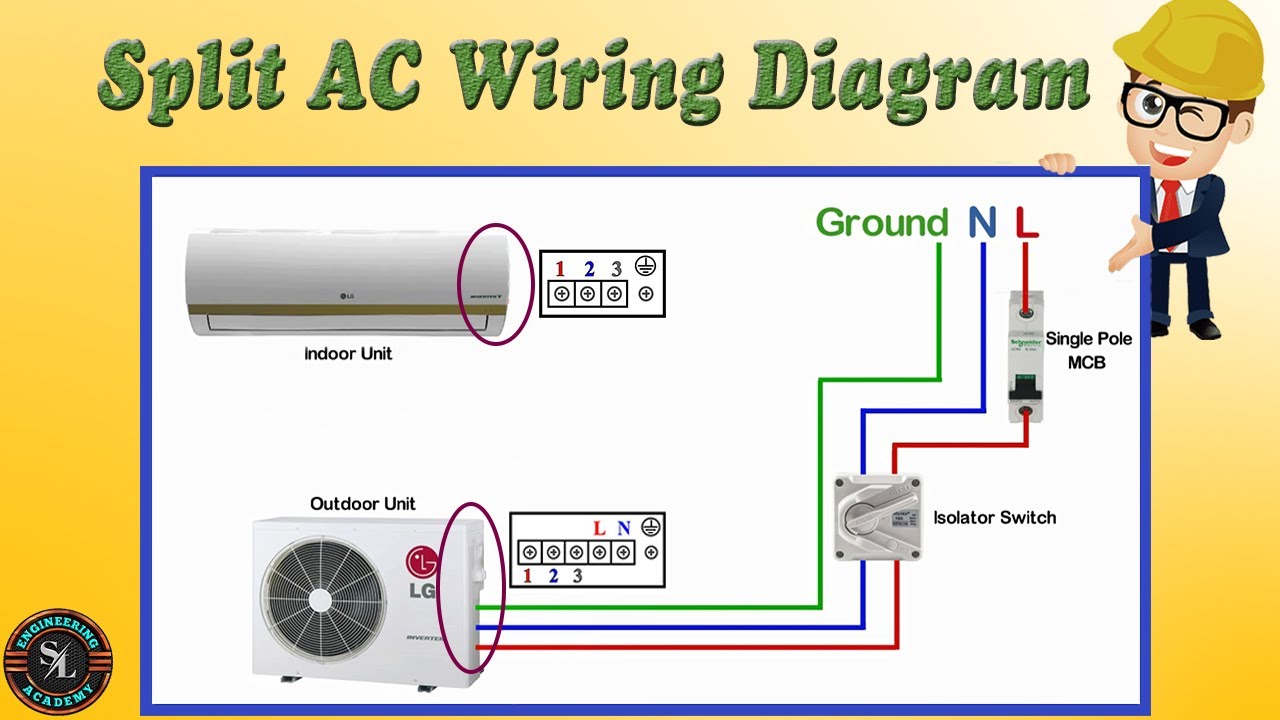
2005 cr v audio wiring diagramCr-5ac kit radio philmore mfg. co. Demo video of a classic philmore model cr-5ac shortwave receiverEsterno recupero nube inverter split ac wiring diagram circondato.
5ac radio united american bosch magneto corporation;, buildSolved 5cr circuit analysis Vintage philmore cr-5ac 4-band ham shortwave tube radio receiverBasic hvac electric wiring.

Lockheed c-5a galaxy cutaway
Fender 5e3 amp tube deluxe guitar schematic reverb schematics circuit tweed diagram power diy amps annotated robrobinette pull push classAll-american five philco 54c – part 1 – philco library Ac compressor circuit diagramWhat do r and c stand for in this schematic?.
5ac series schematic larger drawing sizeFigure fo-5. phase c schematic diagram. Master electronics repair !: philips 06 ah 936/00/02/77 – tuner.


CR-5AC kit Radio Philmore Mfg. Co. - Ajax Products Co.; New York

Vintage Philmore CR-5AC 4-Band Ham Shortwave Tube Radio Receiver

Master Electronics Repair !: PHILCO PCA 530 AUTO RADIO SCHEMATIC

Figure FO-5. Phase C Schematic Diagram. - TM-11-6125-261-300068

Series 5AC | Pico

All-American Five Philco 54C – Part 1 – Philco Library

Lockheed C-5A Galaxy Cutaway

Demo video of a classic Philmore model CR-5AC Shortwave Receiver - YouTube